English
 Deutsch
 한국어
한국어 Русский
 Français
 日本語
日本語 لالعربية
 हिन्दी
 Español
 Português
 繁体中文
繁体中文 简体中文
简体中文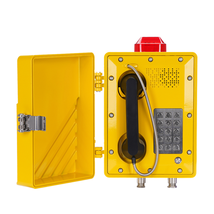


제품
산업용 전화
IP 전화
SIP 인터콤
voip 게이트웨이
sip 서버
페이징 콘솔
경험
리소스
리소스
Becke 커뮤니티에서 모범 사례를 발견하고, 혁신적인 솔루션을 탐색하고, 동료 파트너와 네트워크를 구축하십시오.
 지식
지식
2026-03-13 17:36:42
Analysis of the QoS Mechanism for Ensuring Voice Quality in SIP Amplified Telephones
In-depth analysis of the QoS core technologies of the SIP amplified telephone system, covering DSCP marking, LLQ queue scheduling, jitter buffer configuration, packet loss recovery mechanism, and hardware coordination strategies. Provide practical network configuration parameters, troubleshooting methods, and enterprise deployment best practices.

Becke Telcom
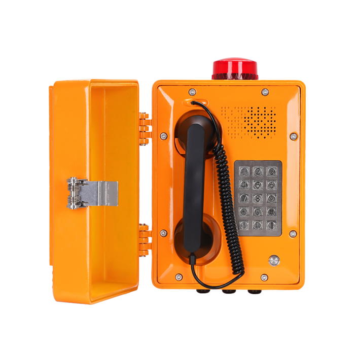
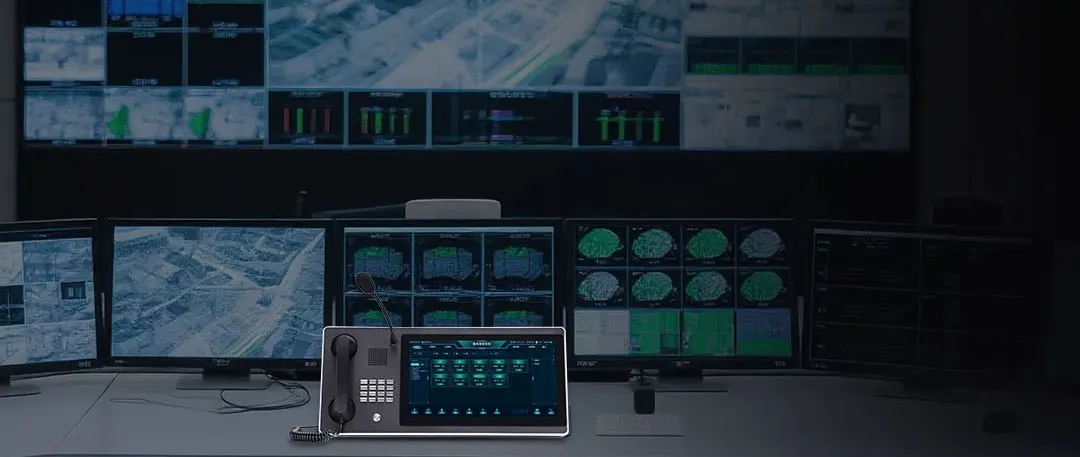
In high-noise, mission-critical communication scenarios such as industrial dispatch, underground mines, port terminals, rail transit, and chemical plant areas, SIP horn speakers are not merely communication tools; they serve as the "lifeline" for production dispatching and the "last line of defense" for emergency command. Such devices typically need to operate in high-power broadcast and full-duplex intercom modes. Facing complex IP network environments—including bandwidth limitations, multiple routing hops, electromagnetic interference, and sudden traffic congestion—ensuring voice quality becomes a core technical challenge.
SIP (Session Initiation Protocol), as the core control protocol for IP communication, was originally designed with a "best-effort" transmission model and does not inherently provide Quality of Service guarantees. When voice streams are encapsulated into RTP (Real-time Transport Protocol) packets and transmitted over IP networks, issues like delay, jitter, packet loss, and bandwidth contention can directly lead to voice distortion, loss of commands, or even communication interruption. For horn speakers, these problems are amplified by the high-power loudspeaker, resulting in an unacceptable user experience.
Therefore, the introduction of QoS mechanisms is precisely aimed at resolving this core contradiction. This article will systematically analyze the implementation principles, key technical parameters, hardware collaboration strategies, and practical deployment solutions of QoS mechanisms in SIP horn speaker systems, providing an in-depth technical reference for building highly reliable industrial voice communication systems.
I. Technical Architecture of SIP Horn Speakers and QoS Challenges
1.1 Special Workflow of Horn Speakers
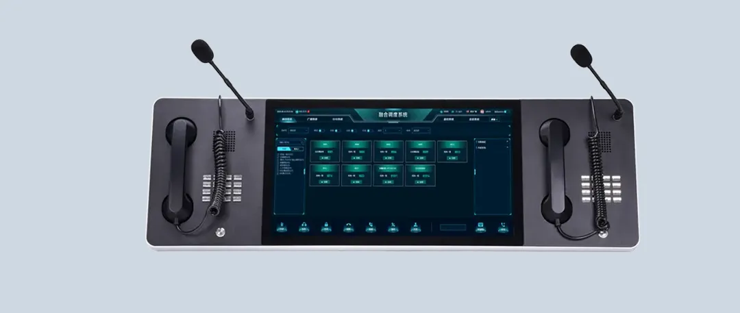
SIP horn speakers differ from ordinary desktop IP phones. They typically integrate high-power loudspeakers (typical power 10W-50W), high-sensitivity noise-canceling microphones, echo cancellation modules, and complex audio processing units (ARM+DSP dual-core architecture). Their workflow consists of four core stages:
- Terminal Registration Stage: All SIP horn terminals send REGISTER requests to the SIP server upon power-on for registration. The server verifies the terminal identity and returns a 200 OK response, completing the registration and marking the terminal status as online. This stage involves the reliable transmission of signaling traffic; registration failure renders the terminal unavailable.
- Session Establishment and Media Negotiation Stage: When initiating a broadcast or intercom, the calling terminal sends an INVITE message containing SDP (Session Description Protocol) content. This includes the list of called terminals (supporting multicast or group broadcast identifiers), supported audio codec lists (e.g., G.711, G.729, Opus), RTP ports, and QoS capability parameters. Upon receiving the INVITE, the target terminal negotiates media capabilities with the caller to determine the mutually supported codec and transmission parameters.
- Media Transmission Stage: After session establishment, an RTP media channel is established between the caller and the called terminal. For broadcast scenarios, the server or media gateway typically duplicates the caller's voice stream and distributes it to all terminals subscribed to that broadcast. For intercom scenarios, a bidirectional RTP stream is established for full-duplex conversation. This stage is the core battlefield for QoS guarantees.
- Session Termination Stage: After the call ends, the caller sends a BYE request to terminate the session, and each terminal returns an acknowledgment response, releasing occupied network resources and DSP processing resources.
1.2 Special QoS Requirements for Horn Speaker Scenarios
The broadcast mode of horn speakers imposes special QoS requirements. In unicast mode, one channel of G.711 encoded voice requires approximately 64Kbps bandwidth; adding IP/UDP/RTP header overhead (IP 20 bytes + UDP 8 bytes + RTP 12 bytes), the actual occupation is about 80Kbps. In broadcast mode, if server duplication and distribution are used, the server's outgoing bandwidth requirement for N receiving terminals is N × 80Kbps. When N reaches 100, the bandwidth requirement can reach up to 8Mbps, posing severe challenges to uplink links and core switch buffers.
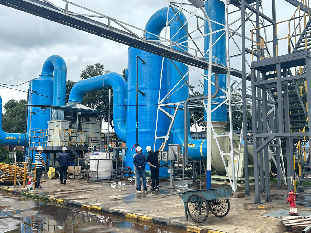
Furthermore, horn speakers in industrial environments are typically deployed in remote field locations, backhauled via wireless bridges, fiber optic rings, or 4G/5G networks. The network topology is complex, with many routing hops, making it easy for end-to-end delay to exceed the 200ms threshold.
1.3 Core QoS Threat Indicators
In SIP horn speaker systems, there are four main QoS indicators for measuring voice quality, and their degradation directly impacts communication reliability:
- Latency: The time required for data to travel from the sender to the receiver. It includes encoding delay (20-30ms), network transmission delay (depending on routing hops and link quality), and jitter buffer delay. ITU-T G.114 recommends controlling one-way delay within 150ms. Exceeding this threshold causes noticeable lack of synchronization during calls, especially in two-way intercoms, severely impacting communication rhythm. For long-distance transmission scenarios like mines or tunnels, complex routing might push delay towards 200ms, necessitating technical intervention.
- Jitter: The variation in packet arrival time, i.e., the standard deviation of delay. Due to the dynamic nature of IP network routing and scheduling uncertainties, packets cannot arrive at strictly uniform intervals. If jitter exceeds 30ms, the receiving end may experience distortion like "stuttering" or "accelerated" speech. For scenarios requiring synchronized playback across multiple terminals (e.g., plant-wide broadcasts), jitter issues are further amplified.
- Packet Loss: The percentage of data packets lost during network transmission. Ordinary voice communication requires packet loss below 1%-3%. However, for horn systems carrying critical commands, packet loss must be controlled within 0.5% or even 0.3%. Exceeding this threshold can lead to missing command words (e.g., "stop" becoming "top"), voice artifacts, or loss of key syllables.
- Bandwidth: The maximum data transfer rate of a network link. Insufficient bandwidth causes voice choppiness, automatic codec downgrading (e.g., switching from G.711 to G.729), and in broadcast mode, can even trigger network congestion collapse.
II. QoS Negotiation Mechanisms at the SIP Signaling Level
Before media stream establishment, the SIP protocol first negotiates QoS requirements via SDP. This is the "first checkpoint" for end-to-end quality assurance, setting the tone for subsequent media transmission.
2.1 QoS Parameter Interaction via SDP
In SIP INVITE messages and 183 (Session Progress) responses, the carried SDP content includes not only IP addresses and ports but also media types, codecs, RTP payload types, and descriptions of QoS resource requirements.
An example SDP basic structure:
- m=audio 5004 RTP/AVP 0 8 18
- a=rtpmap:0 PCMU/8000
- a=rtpmap:8 PCMA/8000
- a=rtpmap:18 G729/8000
- a=status:desired
Where:
The `m=audio` line defines the media type (audio), receiving port (5004), transport protocol (RTP/AVP), and a list of supported payload types (0, 8, 18).
The `a=rtpmap` lines map payload types to specific codecs and sampling rates.
`a=status` is an extension field used to convey QoS requirement status. `desired` indicates a request for resource reservation; if supported, the peer might reply with `available` indicating network resources are ready.Through this mechanism, terminals can explicitly inform the peer of the desired QoS level for this call and negotiate mutually supported encoding parameters.
2.2 Prioritization and Dynamic Switching of Codecs
In the SDP media line, terminals list supported codecs in order of priority. For horn speakers, a trade-off must be made between sound quality and bandwidth usage:
- Good Network Conditions: Prioritize G.711 (PCMU/PCMA) for lossless sound quality (64Kbps), achieving MOS (Mean Opinion Score) above 4.4.
- Bandwidth-Constrained Conditions: Switch to G.729 (8Kbps) to save bandwidth, with MOS around 3.9-4.0, offering slightly reduced but acceptable quality.
- Wireless/Mobile Networks: Use Opus (6-510Kbps adaptive) or AMR-WB (23.85Kbps), which offer better resilience to packet loss and support wideband audio.
More importantly, modern SIP horn systems support dynamic codec downgrading: When the network quality monitoring system detects increased packet loss or jitter, it can initiate a SIP Re-INVITE to renegotiate the codec, downgrading from G.711 to G.729, or even enabling more robust redundancy encoding modes, sacrificing some sound quality for communication continuity.
2.3 Application of RSVP (Resource Reservation Protocol)
In extremely strict QoS requirement scenarios (e.g., military, nuclear power plants, command centers), simple priority marking and codec negotiation are insufficient. The Resource Reservation Protocol (RSVP) is needed, a "hard state" mechanism that reserves network resources along the path for specific data flows.
The workflow of RSVP in a SIP system is as follows:
- The caller sends an INVITE message with SDP, indicating the need for RSVP resource reservation.
- The callee receives the INVITE, calculates the required resources based on the media characteristics in the caller's SDP, and sends PATH messages along the path to the caller.
- Routers along the path record the path state and prepare resources.
- The caller receives the PATH message and sends RESV messages back along the same path. Routers along the way reserve bandwidth and buffer resources hop-by-hop.
- Upon successful reservation, the callee sends a 200 OK, and the media channel is formally established.
Vendors like Cisco enable terminals that do not support RSVP to utilize RSVP for QoS by configuring RSVP Agents on voice gateways. The RSVP Agent acts as a proxy, interacting with Cisco Unified Communications Manager via SCCP to create resource reservations for voice and video media streams.
Although this method increases call setup time (typically by 200-500ms), it provides deterministic bandwidth guarantees, suitable for the highest grade of mission-critical communication.
III. Key Technologies for End-to-End QoS Assurance
Implementing QoS truly relies on hop-by-hop behavior control at the data plane and intelligent adaptation at the terminal side. This section delves into core technologies such as priority marking, queue scheduling, jitter buffer management, and packet loss recovery.
3.1 Priority Marking and DSCP Classification
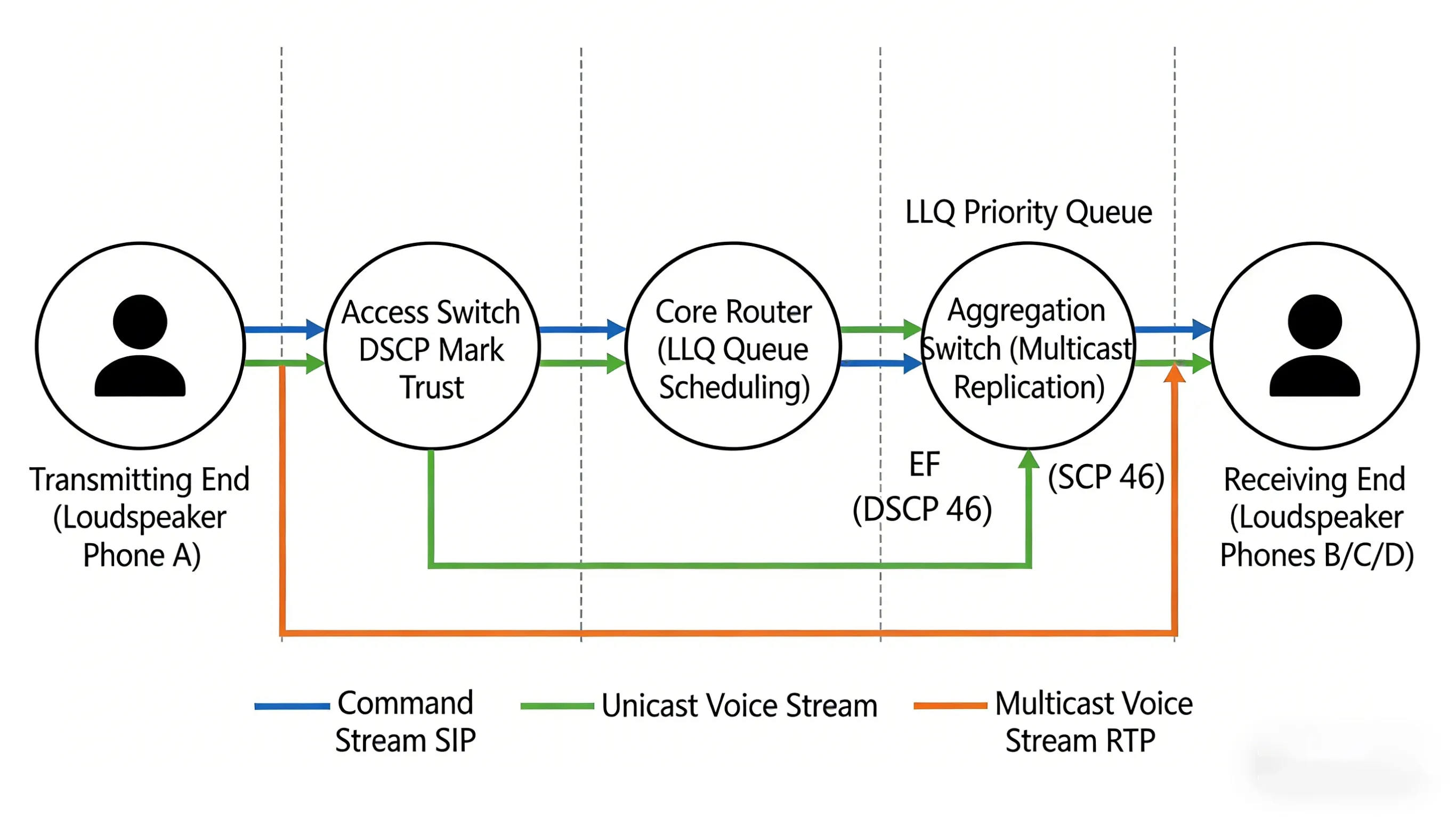
This is the most core technical means within QoS mechanisms. By setting the Differentiated Services Code Point (DSCP) in the header of IP packets, different types of traffic can be given explicit "labels," informing network devices along the path how to handle these packets.
DSCP uses 6 bits in the ToS (Type of Service) field of the IP header, with values ranging from 0 to 63. In SIP horn speaker systems, the following marking strategy is recommended:
| Traffic Type | DSCP Value | PHB (Per-Hop Behavior) | Description |
| Voice Stream (RTP) | 46 | EF (Expedited Forwarding) | Lowest delay, lowest loss, (priority forwarding) |
| Signaling (SIP) | 34-38 | AF4 (Assured Forwarding) | Ensure reliable transmission of call control instructions |
| Video Stream (if any) | 34 | AF4 | Equal or slightly lower priority than signaling |
| Ordinary Data | 0 | BE (Best Effort) | Lowest priority |
At the terminal configuration level, mainstream SIP horn devices (e.g., Polycom, Cisco 8800 series) support setting DSCP values for audio and video calls in SIP configuration files. For example, Cisco IP phones can have DSCP policies dynamically delivered via XML configuration files.
3.2 Queue Scheduling and Congestion Management
Network devices (switches, routers) execute corresponding queue scheduling policies based on DSCP values. During congestion, it is imperative to ensure high-priority voice packets pass through first.
Low Latency Queuing (LLQ) is currently the most effective queuing mechanism in VoIP environments. It places voice streams marked with EF into a strict priority queue, sending them before any other traffic under any circumstances, while also using policing mechanisms to prevent the priority queue from monopolizing bandwidth and starving other traffic.
Cisco device configuration example:
- policy-map VOICE_QoS
- class VOICE_CLASS
- priority level 1
- police cir 1000000
- class SIGNALING_CLASS
- bandwidth percent 10
- class class-default
- fair-queue
- interface GigabitEthernet0/1
- service-policy output VOICE_QoS
Token Bucket Shaping is another key traffic management technique. When traffic exceeds the rated bandwidth, excess traffic is buffered (temporarily stored in a queue) to prevent burst traffic from causing network congestion. Dynamic QoS configuration on the hub side limits the bandwidth of medium-priority traffic, preventing voice stream drops during congestion.
3.3 Dynamic Jitter Buffer Management
To combat network jitter, the receiving end must enable a Jitter Buffer. This technique involves buffering a certain number of received packets and then reading and playing them out at a constant rate from the buffer.
- Static Jitter Buffer: The buffer size is fixed, e.g., always set to 40ms. Advantages are simple implementation and constant delay. Disadvantages are poor adaptability: if set too small, it cannot absorb large jitter; if set too large, it introduces unnecessary delay.
- Adaptive Jitter Buffer: Dynamically adjusts the buffer depth based on real-time network jitter. When increased jitter is detected, the buffer expands from the default 40ms to 80ms or even 120ms to absorb delay spikes; when the network stabilizes, it gradually shrinks the buffer to reduce delay.
Vendors like BeroNet, through their MSP (Media Stream Processor), offer fine-grained jitter buffer configuration parameters:
- delay_min: Minimum jitter buffer size (0-300ms, default 0ms)
- delay_max: Maximum jitter buffer size (0-300ms, default 200ms)
- delay_init: Initial buffer size when the voice channel starts (0-300ms, default 0ms)
- adaption_period: Time period for adaptive jitter buffer adjustments (1000-65535ms, default 10000ms)
- deletion_mode: 0=Soft mode (prioritize sound quality, accept slightly higher delay), 1=Hard mode (strictly limit delay)
- deletion_threshold: Late packets exceeding this jitter value are directly discarded (0-500ms, default 500ms)
By fine-tuning these parameters, an optimal balance between delay and smoothness can be found. For example, for delay-sensitive control commands, a smaller `delay_max` and `deletion_mode=1` can be set; for broadcast playback, a slightly higher delay can be accepted in exchange for smooth playback.

3.4 Packet Loss Recovery and Error Correction Techniques
Even in networks with QoS guarantees, packet loss is difficult to completely avoid, especially in wireless, microwave, or noisy industrial sites. Packet loss recovery techniques fall into two main categories: sender-side active protection and receiver-side passive concealment.
- Forward Error Correction (FEC): The sender inserts redundant information into the data stream. Even if the receiver loses some data packets, the voice can be reconstructed using the redundant packets. Technologies like Super Error Correction (SEC) used by vendors like Huawei, employing techniques like associated checks and interleaved grouping, can ensure basic intelligibility under 3%-10% packet loss conditions. The cost of redundancy encoding is increased bandwidth consumption (typically 30%-50%), requiring activation only when network conditions permit.
- Interleaving: Scrambles consecutive voice frames and transmits them at intervals, converting burst packet loss into random loss, which is easier for the receiver to recover. For example, sending 10 voice frames in the order 1,4,7,2,5,8,3,6,9,10 means that even if 3 consecutive packets are lost, the receiver can still recover most of the information.
- Multiple Description Coding (MDC): Encodes one voice stream into multiple independent substreams (descriptions), each containing approximately complete voice information. Receiving any single description allows reconstruction of intelligible voice; receiving more descriptions allows synthesis of higher quality. MDC offers extremely strong resilience to packet loss but comes with high encoding complexity and bandwidth overhead.
- Packet Loss Concealment (PLC): The receiver uses algorithms based on the correlation between preceding and subsequent packets to interpolate and fill in missing voice frames, masking audible artifacts. Waveform Similarity Overlap-Add (WSOLA) and Pitch Synchronous Overlap-Add (PSOLA) are mainstream implementation algorithms. Gain-controlled WSOLA (GWSOLA) further optimizes amplitude smoothing at (splice points), significantly improving subjective listening experience.
3.5 Acoustic Echo Cancellation Technology
Due to the close proximity of loudspeaker and microphone and the high volume, echo issues in horn speakers are far more severe than in ordinary phones. Acoustic Echo Cancellation (AEC) is a mandatory function.
The core principle of AEC is: The signal played by the loudspeaker (reference signal) is picked up by the microphone, becoming part of the echo. The AEC module estimates the echo path (room acoustic response) using an adaptive filter and subtracts the estimated echo component from the microphone input signal.
A key parameter is Tail Length, which is the length of the echo path the filter can cover. For horn speakers, tail length typically needs to be set to 64-128ms, corresponding to larger spaces with longer reverberation times. Adaptive filter algorithms (such as NLMS, APA) continuously adjust coefficients to make the output signal approach the desired signal, ultimately achieving high-fidelity, high-clarity, carrier-grade voice quality.
IV. Hardware Collaboration and Resource Reservation
QoS for SIP horn speakers is not only about software and network protocols; hardware-level collaboration is equally critical.
4.1 ARM+DSP Dual-Core Architecture
High-end SIP horn speakers typically employ an ARM+DSP dual-core architecture:
- ARM Processor: Responsible for control plane tasks such as SIP protocol stack handling, signaling interaction, network stack management, and user interface.
- DSP (Digital Signal Processor): Dedicated to media processing tasks like voice encoding/decoding, acoustic echo cancellation (AEC), noise suppression, jitter buffer management, and packet loss concealment.
This division of labor ensures that even when the ARM CPU is under high load (e.g., handling multiple simultaneous call signaling, web management access), voice processing remains real-time and reliable, free from interference.
4.2 Power Amplifier and QoS Policy Linkage
Further optimization is reflected in intelligent linkage with the power amplifier. Mine-use horn systems often select the TPA3007D1 Class D power amplifier, which features a shutdown function controllable via pins to achieve low-power modes.
When the network detects persistently high packet loss (e.g., exceeding 3%), the system can automatically reduce the power amplifier's output through hardware control pins, preventing excessive amplification of noise or the generation of harsh, screeching feedback sounds under poor network conditions. Conversely, when the network recovers, the system restores full power output to ensure broadcast coverage. This linkage mechanism between hardware and QoS policies achieves coordinated optimization of network layer quality and physical layer output.
4.3 Multicast Replication Optimization
For broadcast scenarios, the traditional server replication and distribution model suffers from bandwidth amplification effects. Modern SIP horn systems support Multicast technology: the caller only needs to send one RTP stream to a multicast address. Network switches supporting IGMP automatically duplicate packets to all ports subscribed to that multicast group.
In multicast mode, the server's outgoing bandwidth is independent of the number of terminals, greatly conserving core network bandwidth. Vendors like Huawei (ensure) QoS for multicast voice streams by configuring multicast bandwidth allocation (static/dynamic) and priority marking at the network edge, preventing competition with unicast traffic.
V. Quality Monitoring and Troubleshooting
After deploying QoS mechanisms, continuous monitoring is essential to verify their effectiveness and quickly locate fault points when problems occur.
5.1 Key Indicator Monitoring and Alert Thresholds
Deploy voice quality monitoring systems (e.g., SolarWinds, PRTG, Huawei eSight) to track the following indicators in real-time and set alert thresholds:
| Indicator | Normal Range | Alert Threshold | Critical Threshold |
| MOS (Mean Opinion Score) | 4.0-5.0 | <3.5 | <3.0 |
| R-Factor (Transmission Quality Factor) | 80-100 | <70 | <60 |
| Packet Loss | <0.5% | >1% | >3% |
| One-way Delay | <150ms | >200ms | >300ms |
| Jitter | <30ms | >50ms | >80ms |
RTCP-XR (RTP Control Protocol Extended Reports) is an important mechanism for obtaining these indicators. Terminals periodically send reception statistics reports to the peer or server via RTCP packets, containing information like packet loss rate, jitter, and round-trip delay, enabling end-to-end quality visualization.
5.2 Signaling and Media Stream Analysis Tools
Wireshark is a fundamental tool for troubleshooting SIP/RTP issues. Key filtering技巧 (techniques):
- `sip`: Filter all SIP signaling.
- `rtp`: Filter all RTP media streams.
- `udp.port == 5060`: Filter traffic on the default SIP port.
- `rtp.paytype == 0`: View RTP packets encoded with G.711.
- Using "Telephony → VoIP Calls" provides a visual representation of call flows and media quality.
Sngrep is a terminal-friendly SIP signaling analysis tool supporting real-time packet capture and visualized session flow diagrams.
5.3 Typical Fault Scenarios and Resolution Paths
| Symptom | Possible Cause | QoS Investigation Direction |
| One-way Audio | NAT traversal failure, firewall blocking RTP, SDP negotiation failure | Check if SDP (c= line) in SIP signaling contains correct IP; verify firewall opens RTP port range (e.g., 10000-20000); verify if media (stream) is passing through RTP proxy relay |
| Choppy, Stuttering Voice | Network congestion causing packet loss, jitter exceeding buffer capacity, insufficient bandwidth | Analyze RTP sequence numbers in capture files for gaps; check core switch ports for errors; verify if DSCP marking (46/EF) is being altered by network devices. |
| Severe Echo | Acoustic Echo Cancellation (AEC)失效 (failure), network delay exceeding AEC tail length | Check if terminal AEC is enabled (must be enabled for hands-free mode); measure network round-trip delay (RTT); if RTT >200ms, echo might exceed AEC tail length coverage. |
| Call Drops/Intermittent | SIP registration timeout, network glitch, session timer expiry | Adjust SIP registration interval (register = 3600); (check) core links for errored seconds; verify SBC/proxy server session timer (session-expires) configuration. |
| Registration Failure (401 Unauthorized) | Incorrect credentials, clock synchronization issue, Nonce expired | Verify username and realm in Authorization header; synchronize terminal and server time (NTP service); extend Nonce lifetime on proxy server (e.g., FreeSWITCH's nonce-lifetime=3600). |
5.4 Automated Testing Tools
SIPP: Industry-standard SIP protocol performance testing tool, can simulate high-concurrency calls to test proxy server performance:
sipp -sf uac.xml 192.168.1.1:5060 -p 5060 -s 1001 -r 10 -rp 2s
iperf3: Network bandwidth and jitter testing tool, useful for evaluating the underlying network's capacity to carry voice streams.
PJSIP command-line tools: Test registration and call functionality via pjsua, supporting scripted automated testing.
VI. Enterprise-Grade Deployment Best Practices
Based on the preceding technical analysis, this section proposes a complete implementation framework for QoS assurance in SIP horn speaker systems.
6.1 Phased Deployment Strategy
- Phase 1: Foundational Network Optimization. Before deploying the SIP horn system, resolve underlying network issues: ensure sufficient link bandwidth, low bit error rates, and fast route convergence; deploy NTP services for network-wide time synchronization; enable Spanning Tree Protocol optimizations (PortFast, BPDU Guard) on switch ports to prevent topology changes from causing voice interruptions.
- Phase 2: QoS Policy Deployment. Uniformly deploy DSCP marking trust policies and LLQ queue scheduling on core routers and switches; deploy port rate limiting and storm control on access layer switches; deploy bandwidth reservation and congestion avoidance (WRED) on edge routers.
- Phase 3: Terminal Parameter Tuning. Configure terminal jitter buffer parameters based on site network conditions (suggest initial 40ms, max 120ms), codec priority lists (G.711 (preferred)), AEC tail length (64-128ms); enable RTCP-XR reporting for centralized monitoring.
- Phase 4: Continuous Monitoring and Optimization. Deploy a voice quality monitoring platform, establish baselines for MOS, packet loss, and delay;定期 (periodically) analyze quality indicators in CDRs (Call Detail Records); perform targeted optimization for (anomalous) areas.
6.2 Redundancy and Disaster Recovery Design
- Active-Active SIP Proxies: Deploy two SIP proxy servers, implementing automatic failover via DNS SRV or load balancers.
- Media Server Redundancy: RTP relay and transcoding resources adopt N+1 redundancy design.
- Link Redundancy: Key nodes use dual-link access, achieving gateway redundancy via VRRP/HSRP.
- Codec Downgrade Contingency Plan: Preset automatic switching to low-bandwidth codecs (G.711 → G.729 → Opus 12kbps) when network deteriorates, prioritizing communication continuity.
6.3 Adherence to Standardized Protocols
Adhering to RFC standards avoids vendor interoperability issues. Key standards include:
- RFC 3261 (SIP Core Protocol)
- RFC 3550 (RTP/RTCP)
- RFC 4566 (SDP)
- RFC 6076 (SIP Event Notification)
- RFC 2205 (RSVP)
Conclusion
Ensuring voice quality for SIP horn speakers is by no means achievable through a single technology. It is an end-to-end(system engineering challenge), ranging from signaling negotiation (SDP/RSVP) to data marking (DSCP), from queue scheduling (LLQ/WFQ) to terminal adaptation (Jitter Buffer/PLC), and extending to hardware collaboration and real-time monitoring.
In the context of Industry 4.0 and digital transformation, when enterprises deploy SIP horn systems, they should not only focus on the device specifications themselves but also integrate QoS planning into the initial stage of network design. Through (meticulous) DiffServ policy划分 (delineation), reasonable bandwidth planning, fine-tuning of terminal parameters, and continuous quality monitoring, SIP horn speakers can fulfill their maximum value as mission-critical communication tools, providing reliable assurance for safe production and efficient dispatch, even in challenging industrial network environments.
레이블:


이메일 주소:
핫라인: